

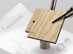
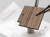
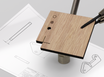
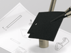
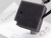

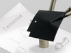
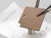
In this tutorial you will learn how to make a laser drawing from a 3D SketchUp Model. As an example we use a simple facade for an architectural model (scale model).

SketchUp is a computer program that can be used to draw in 3D. It is a relatively cheap program compared to other programs and it is easy to learn. It is available for Windows and OSX. A 3D SketchUp model consists of a .skp file format but can also import and export .pdf and .dwg drawings.
There are different versions of SketchUp: SketchUp Pro and SketchUp Free . SketchUp Pro has more functions but unlike SketchUp Free it is not free. SketchUp Free is an online version of SketchUp Pro, handy if you want to try out the program!
SketchUp is:
- Easy to learn (many tutorials can be found on the internet)
- Suitable for drawing in 3D and 2D
This tutorial uses SketchUp Pro.
Getting Started
Download our SketchUp template here . The layers and styles are set up here so you can get started right away. Now you can start drawing!- Draw your 3D model in scale 1:1, or convert your existing 3D Model to scale 1:1 by scaling it. In this tutorial, the model is drawn as it will look in reality, including the thickness of the material to be lasered. This way you can immediately see what your model will look like.


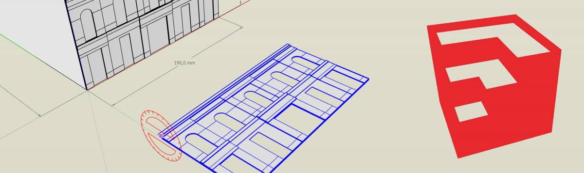
From 3D to 2D
- Convert your 3D model from 3D to 2D. You can do this by rotating the different parts and placing them in a flat plane.
- If you need different parts of the same material, you can merge them into one drawing (nesting). Pay attention to the maximum size of the material you are going to use. You can draw parts all the way to the edge of the plate size.
- When nesting, leave a small space between the parts: at least 2 mm (4 mm for foam).
- Draw a frame of cutting lines along the edge of your drawing for a neat edge. If you do not draw a frame, we will position the drawing on a plate as we see fit. It is possible that the edges of the plate are sawn instead of lasered.
Tip: If you use 'Components' in the 3D model of the maquette and copy it to the 2D plane, you will immediately see the adjustments you make in the 2D plane reflected in the 3D model.


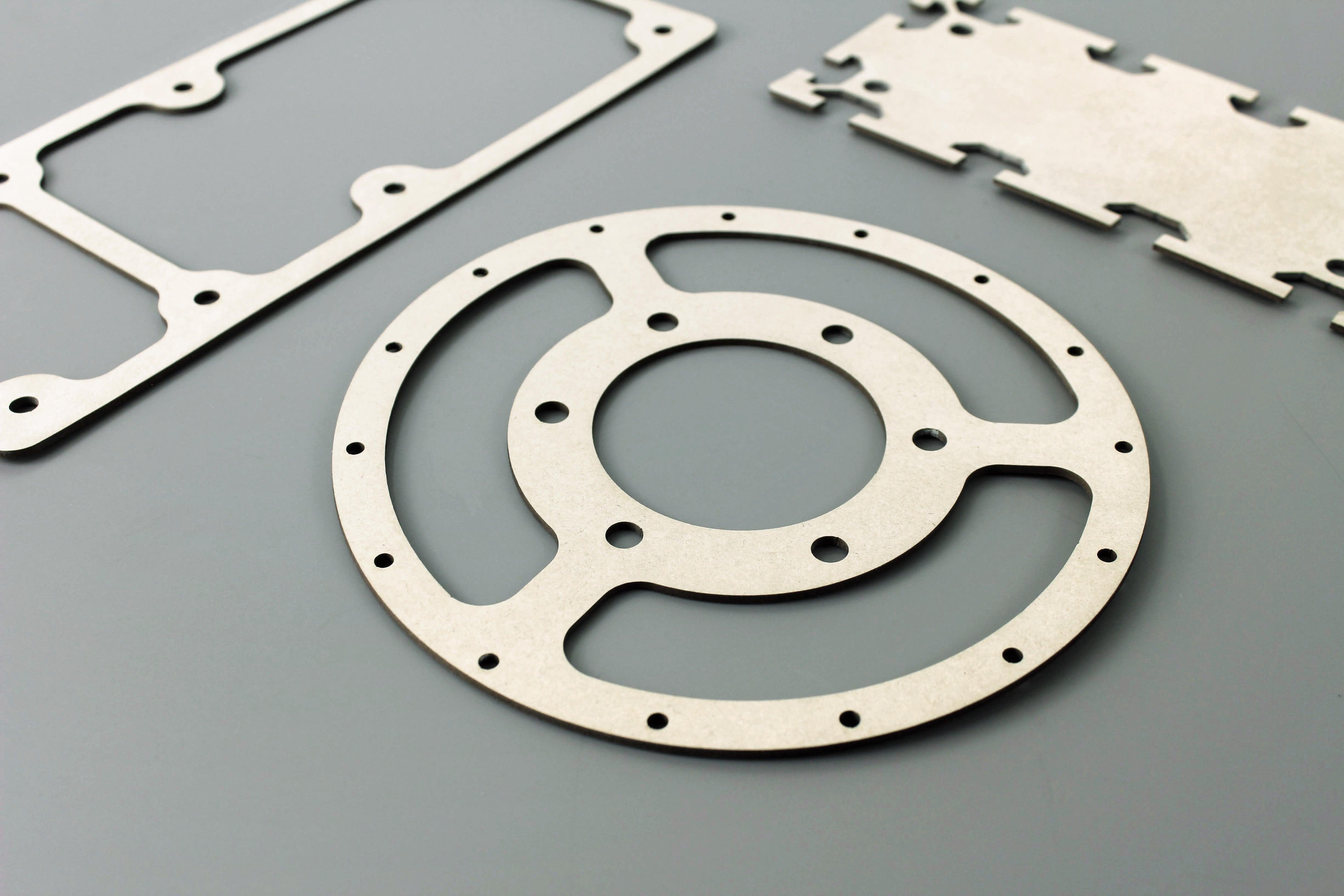
Cutting or engraving
The distinction between cutting and engraving is made on the basis of colours:
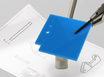
- Blue (RGB 0,0,255) lines are cut
- Red (RGB 255,0,0) lines are engraved as line
- Magenta (RGB 255,0,255) closed lines are engraved as a plane
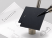
- Gray (RGB 128,128,128) lines are ignored (useful as guide lines, or help text)
Please note: Unrecognized colors and layer names are automatically read as 'cutting'. These lines are shown blue in the preview.
In order to export the lines with a color, it is important in which layers the objects are located (see the drawing rules ).
Draw according to the drawing rules in the correct layers:
- Place cutting lines in the ' cutting ' layer
-
Place engraving lines in the ' line engraving ' layer
- Place engraving areas in the ' engraving area ' layer
- Put all lines and ' faces ' that should not be cut or engraved in the ' ignore ' layer
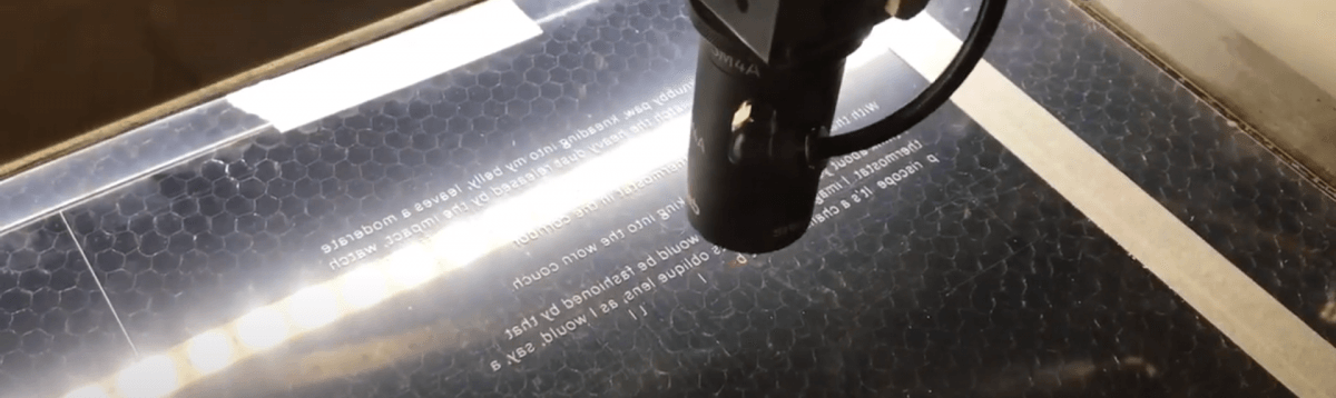
- Text must be converted to lines before it can be cut or engraved.

Adjust line color in 'Styles'
To display the colors of the lines from the different layers with the correct color, you will have to adjust the display settings in 'Styles'. In the SketchUp template, a Style has already been created with the correct settings called 'Laser cutting'.
- Go to Window > Styles

- Under Styles, select 'Laser Cutting'
Check that:
- At the Edge Settings
- In the Modeling Settings
- The Layers have the correct 'Material Color' and the color of the lines is now correct.


Save as .pdf
- Make sure the 'Camera' is set to 'Parallel Projection' instead of 'Perspective'.
Camera > Parallel Projection
- Set the 'Camera' to 'Top View'.
Camera > Standard Views > Top


- File > Export > 2D Graphic…
- Click on Options…
Check whether:
- Image Scale the correct scale is set: 1.0 mm 'In Image' = 1.0 mm 'In Model'
- Line Quality the Line Scale is at 0.5
- Click OK
- Click on Export


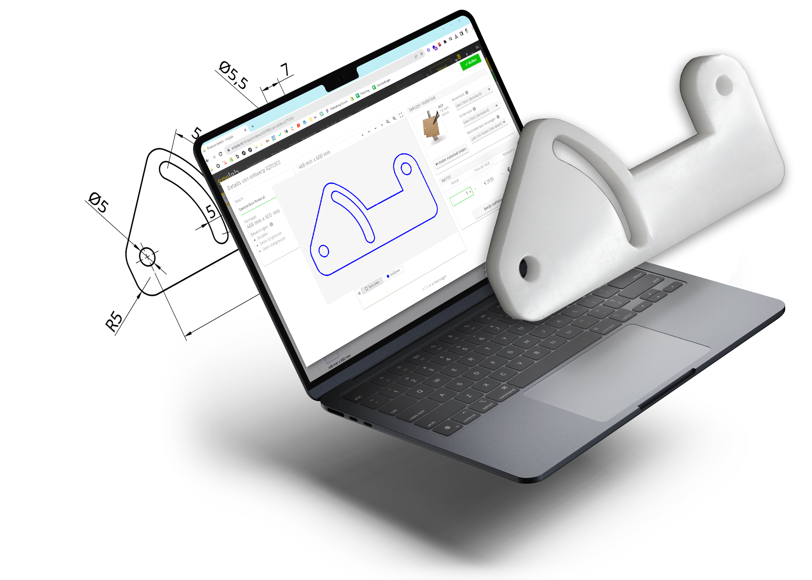
Upload
On our website, drag the .pdf file into the upload field.
Please check carefully whether:
- the size is correct
- the colors of the preview match the intended edits
Blue = cut completely
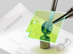
Red = line / vector engraving
Magenta = flat engraving
Gray = no editing / layer to ignore
Please note: Unrecognized colors and layer names are automatically read as 'cutting'. These lines are shown blue in the preview.

